Duplex stainless steels possess high strength and toughness, as well as good resistance to intergranular corrosion, stress corrosion, and corrosion fatigue. They are widely used in fields such as petrochemicals, offshore chemical product storage tanks, and seawater heat exchangers. Among duplex stainless steels, SAF2205 is the most widely used, while the super duplex stainless steel SAF2507 has gained increasing attention due to its superior corrosion resistance [1]. The mechanical properties and corrosion resistance of duplex stainless steel welded joints depend on whether an appropriate austenite-ferrite ratio can be maintained in the joint. When the proportion of austenite and ferrite is close to 50% each, the performance is optimal. If more ferrite is retained in the weld seam and heat-affected zone after welding, the tendency for intergranular corrosion and susceptibility to hydrogen-induced cracking (embrittlement) may increase [2]. This paper provides a comparative analysis of the microstructure and properties of the base metal, weld seam, and heat-affected zone of SAF2205 and SAF2507 duplex stainless steels after welding, as used in chemical containers.
-
Welding Tests and Weld Composition
Both SAF2205 and SAF2507 were welded using the shielded metal arc welding (SMAW) process. The groove was prepared in an X-shape, and multi-pass welding was employed. The electrodes used were E2209 and E2594, respectively. After welding, a visual inspection of the joints was conducted, revealing no defects such as undercut, cracks, lack of fusion, incomplete penetration, porosity, or slag inclusions. The weld reinforcement height ranged from 1 to 3 mm. The measured chemical compositions of the post-weld SAF2205 and SAF2507 weld seams are shown in Table 1.
Tab.1 Weld seam composition fo SAF2205 and SAF2507(wt%)
Elements C Si Mn Cr Ni Mo N SAF2205Weld Composition 0.03 0.54 0.2 25.4 9.4 3.98 0.24 SAF2507Weld Composition 0.02 0.51 1 23.4 8.6 2.97 0.16 -
Post-Weld Microstructure
2.1 Metallographic Structure
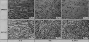
After welding, metallographic analysis was conducted on the weld zone, heat-affected zone, and base metal of the welded joints. The etchant used was a mixed solution of potassium ferricyanide and sodium hydroxide. The results are shown in Figure 1. The microstructures of SAF2205 and SAF2507 base metals are similar, with the austenite phase distributed in an island-like pattern within the ferrite matrix. However, under the same welding conditions, the microstructures of the weld zones and heat-affected zones of the two materials differ significantly. The weld zone and the heat-affected zone of SAF2205 are coarser compared to those of SAF2507 and exhibit Widmanstätten structure characteristics, which can easily lead to embrittlement of the joint.
2.2Phase Ratio
Duplex stainless steels exhibit better corrosion resistance, especially against chloride ion corrosion, compared to austenitic and ferritic stainless steels. The primary reason lies in their unique phase structure and phase ratio. Therefore, the phase ratio in welded joints is one of the most critical indicators for evaluating welding quality. In this study, the phase ratios in different regions of the two materials were determined using the area method via material micrography and metallographic analysis. The results are shown in Figure 2. The ferrite contents in the base metal, weld zone, and heat-affected zone of SAF2205 are 58%, 51%, and 65%, respectively, while those for SAF2507 are 47%, 47%, and 49%, respectively. The phase ratio in the weld zone of SAF2507 is the same as that of the base metal. The difference in the heat-affected zone compared to the base metal is only 2%, and it is closer to 50%. For SAF2205, the phase ratio in the weld zone is 7% lower than that of the base metal, closer to 50%, which is more favorable than the base metal ratio. The phase ratio in the heat-affected zone is 7% higher than that of the base metal, exceeding 60%. The phase ratios in the weld zones of both materials largely depend on close to 50%. The phase ratio in the heat-affected zone of SAF2205 is more significantly affected by welding, while that of SAF2507 is less influenced, resulting in a more stable phase ratio.
3. Mechanical Properties
The mechanical properties of welded SAF2205 and SAF2507 duplex stainless steels are shown in Table 2. The tensile specimens of SAF2205 fractured in the heat-affected zone, whereas those of SAF2507 fractured in the base metal. The mechanical properties of the heat-affected zone in SAF2205 are more significantly influenced by welding heating.
4. Corrosion Tests
The corrosion behavior of SAF2205 and SAF2507 duplex stainless steel welded joints was tested by immersing them in a 6 wt% FeCl3 corrosion solution. Pitting corrosion specimens with dimensions of 10mm×8mm×2mm were cut from the base metal, heat-affected zone, and weld zone of the welded joints. The specimen surfaces were smooth, and pitting corrosion tests were conducted according to the ASTM G84 standard. The test temperature was (22±1)∘C, and the test duration was 24 hours. The corrosion performance of the two materials was compared using the weight loss method. The corrosion test results are shown in Table 3. The data in the table indicate that the corrosion resistance of the base metal, heat-affected zone, and weld zone of SAF2507 is significantly better than that of the corresponding regions in SAF2205. The corrosion rates did not exceed the 10 mg/(dm2⋅d) limit specified in the ASTM G84 standard, and no pitting was observed on the surfaces. Both joints exhibited good corrosion resistance.
During the first welding pass, the softened zone is located approximately 4 mm from the weld centerline, with a width of about 1 mm and a softening magnitude of approximately 11%. After the second welding pass, heat diffuses outward, causing the softened zone to shift outward to around 6 mm, with its width increasing to 1–2 mm. The softening magnitude remains largely unchanged, while the hardness in other areas also decreases. After the third welding pass, heat continues to diffuse outward, resulting in a softened zone located between 5 mm and 9 mm from the weld centerline, with a softening magnitude of about 15%.
The tensile performance of the welded joints was tested using strip specimens as shown in Figure 1 and a CSS-44000 electronic universal testing machine. The results are presented in Table 3. It can be seen that the strength of the ER50-6 low-matching wire welded joint decreases by about 10%, and the elongation decreases by approximately 25%. The fracture occurs in the heat-affected zone. For coiled tubing subjected to plastic strain during operation, such mechanical inhomogeneity may lead to strain concentration in the softened heat-affected zone, thereby reducing the tensile and fatigue performance of the joint [7]. Therefore, when developing welding procedures, the influence of the welding thermal process on the heat-affected zone should be fully considered to achieve a more uniform strength distribution in the welded joint, thereby improving its tensile performance.
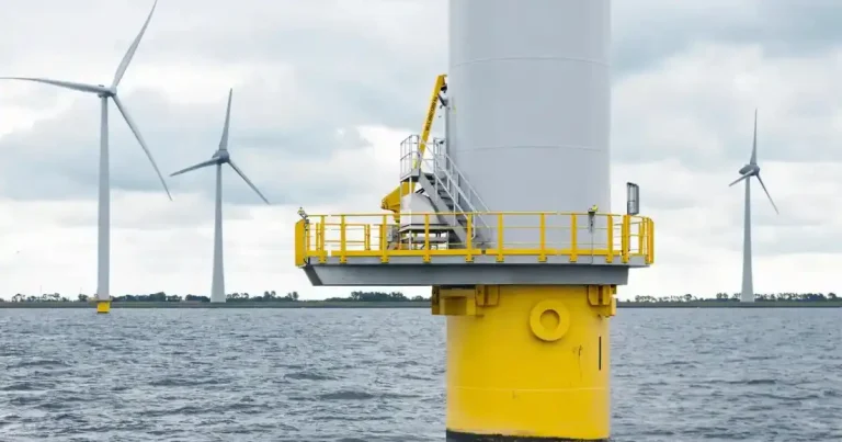
Walkway gratings provide safe and easy access for personnel and are an essential element of offshore structures in the oil and gas industry. Demand has also increased considerably in recent years thanks to the growth of offshore wind.
HDG gratings are the most used solution. They are available as ready-to-use, cut-to-length, products to cover the required surface area. The other candidate material in this application, glass fiber reinforced plastic (GRP), is not fire resistant, doesn’t have the same strength, and can’t withstand low temperatures.
HDG (Hot-Dipped Galvanized) gratings are the most used solution.
The challenge with using HDG gratings offshore is the constant exposure to salt spray and wide variations in temperature. These mean that they generally require frequent maintenance and replacement. This is encouraging the industry to look at stainless steel that can offer a maintenance-free solution capable of lasting the long design-life of 30 years or more expected for offshore structures.
Crevices are inherent in the design of gratings. That rules out the use of 316L as this austenitic grade is sensitive to crevice corrosion in marine environment. However, an attractive option is to use a duplex stainless steel that combines many of the beneficial properties of ferritic and austenitic stainless steels. In particular, the duplex microstructure contributes to a high mechanical strength and high resistance to stress corrosion cracking.
Forta comes to the fore
Initial projects for offshore gratings have used Outokumpu’s Forta EDX 2304. It has high strength and elongation – Rp0.2 ≥ 500 MPa, A5 ≥ 25 %. Furthermore, it has a higher chromium content in comparison to austenitic grades, giving it higher pitting and crevice corrosion resistance than 316L. An added benefit is its lower nickel content, which is an alloying element subject to significant fluctuation in pricing, so it has a much more stable price.
It should be noted we do not recommend that Forta EDX 2304 is deployed close to seawater in the splash zone. For the best corrosion performance, it needs to be around 10 to 15 meters above the seawater level in areas where there is consistent flushing by rainwater.
For more severe applications we would suggest Forta DX 2205, and if the grating is in the splash zone and potentially in contact with seawater then a step up to super duplex Forta SDX 2507 is recommended.
Suitability for welding
Two welding methods are in general use for the manufacture of walkway gratings: shielded metal arc welding (SMAW) and manual arc welding (MAW), both are carried out with stick electrodes. Duplex stainless steels have, in general, very good weldability and are compatible with most welding methods used for stainless steel grades.
Weight-saving potential
An important advantage of duplex grades is high strength, which enables light-weighting. To evaluate its potential, trials have been carried out with manufacturers to substitute lean duplex material in their existing HDG grating designs. The two critical criteria for walkway gratings are load carrying capability and deflection.
Tests performed with varied loadings over a pre-set span have confirmed that gratings manufactured in lean duplex stainless meet the load and deflection requirements with a reduced section (30 x 3mm compared with 30 x 5mm for HDG steel). This offers the potential for a weight saving of up to 40%.
The key implication of this weight saving is that duplex stainless steel presents an attractive option for modification projects. This is because a key driver for these projects is to not increase the total weight of the platform to avoid the need for rebalancing.
Furthermore, the significant potential saving in the construction of a new structure could allow the installation of additional equipment with no additional weight burden. Reduced weight could also allow the possibility for structures to be built onshore and then transported more easily to an offshore installation.
Reducing environmental impact and carbon footprint
Utilizing duplex grades in production instead of carbon steel solutions with painted or HDG surfaces will minimize pollution and hazardous waste as stainless steel does not require surface treatment. The longer life cycle, compatible with the 20-year plus life of offshore installations, makes it a superior environmental choice over carbon steel that will require regular maintenance and possible replacement. The increased life expectancy of the duplex material will also improve the carbon footprint of the project. Long life and low maintenance are also very significant factors in optimizing the total cost of ownership (TCO) of the project.
Faster installation
Avoiding the need for welding operations can generally allow faster installation for offshore projects. This can be achieved with duplex material with bolted connections and has a direct impact on the labor time required, resulting in cost savings. Furthermore, when HDG gratings are cut or modified during construction or modification the cut surfaces require treatment against corrosion, which is not needed for stainless steel.
The ideal choice for specific applications
In some offshore applications, minimizing the weight of walkways is the top priority so GRP will continue to be used. In other cases, where long life and low maintenance are not critical, then HDG will remain the natural choice. The role of duplex steel is to offer an interesting new alternative for walkways in more demanding applications. This is where its combination of high strength, light weight and corrosion resistance makes duplex steel a particularly attractive option for achieving the optimum total cost of ownership (TCO).
The choice of material for gratings can also have a significant impact on the sustainability of the project. At the end of life, GRP has no residual value, leaving operators with waste that is troublesome to process. In contrast, stainless steel is fully recyclable so the gratings will retain considerable value even after a long service life.
(Excerpt from an interview with Outokumpu)

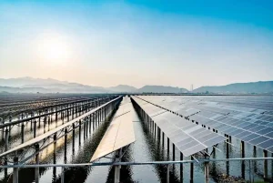
Marine structures are not only critical for oil and gas exploration, they are growing in importance for the renewable energy sector. This includes floating solar schemes as well as offshore wind farms that can be sited well over 10 km from shore. Corrosion is a major issue for these structures as they are exposed to a chloride-rich environment, wet-dry cycles, high humidity, and microbiological attacks. They may also be subjected to abrasion and wear from sand, floating waste and currents. Material selection, together with the methods used to protect against corrosion protection, therefore plays an important role in determining the reliability, maintenance needs and lifetime of structures which are often expected to stay in service for 20 to 25 years or more.
raditionally, carbon steel has been protected against the corrosive marine environment by applying a coating. This adds to the initial fabrication cost, while a corrosion allowance is often added to the wall thickness, resulting in increased material costs. Furthermore, coated carbon steel structures typically require maintenance such as recoating, replacement of corroded steel plates and repair work during their service life. Switching to stainless steel, with its inherent corrosion resistance, offers the potential to reduce life cycle costs as well as the impact on health and safety and the environment.
Rather than the conventional 304L and 316L grades, using higher strength duplex stainless steel offers particular advantages for marine structures. This family of materials combines both austenitic and ferritic microstructures to offer the best properties of each main type of stainless steel: corrosion resistance and high strength. This allows the design of lighter structures based on thinner gauges.
In addition to saving weight and material cost, duplex grades offer further advantages such as extended fatigue life and high hardness that gives better resistance to wear and erosion. In addition, duplex grades contain a lower amount of nickel compared to both standard austenitic and high-performance austenitic stainless steel, which means they have less volatile pricing. The performance advantages of higher strength duplex grades are illustrated in Figure 1.
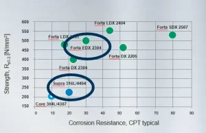
Figure 1 – Comparison of strength and corrosion resistance of stainless steel grades – the Forta grades are duplex stainless steels. CPT is the critical pitting temperature in degrees Celsius at which corrosion starts, it is a useful measure that helps design engineers compare the likely performance of different materials.
Since the corrosion resistance of duplex stainless steel doesn’t depend on an external coating, the risk of failures caused by possible damage to the coating can be avoided. This is important, especially in offshore structures where limited access makes inspections and repair work hard to carry out.
A cost-effective solution
Duplex stainless steel has a higher initial cost compared to carbon steel, so will not seem appealing to a designer that considers only the material price per tonne. However, that does not show the true story as using duplex grades will make a significant impact over the life of a structure through reduced weight, longer lifetime and less maintenance. This is illustrated in Figure 2.
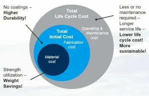
Figure 2 – It is important to compare duplex stainless steel and carbon steel on a total Life Cycle Cost (LCC) basis
It is important to make comparisons on a case-by-case basis. Even so, our experience is that the potential weight saving from switching to lean duplex stainless steel can offer savings of between 30 to 40%. That is before the LLC costs are taken into consideration.
Welding duplex stainless steels – not difficult, but different
The welding of duplex stainless steel is not particularly difficult. But it is different to other steels. In fact, the weldability and welding characteristics of duplex stainless steels are better than those of ferritic steels, although not generally as good as austenitic steels. The properties of a duplex weldment are strongly affected by the welding parameters such as heat input. Therefore, it is vital to establish the correct welding procedures to obtain a structure that delivers the required strength and corrosion-resistance.
Galvanic corrosion is not a major concern
There are concerns about galvanic corrosion when stainless steels are in contact with other metals such as carbon steel, galvanized steel, copper and brass. However, duplex stainless steel is not typically attacked in this way since it is usually the most noble material in the galvanic couple. Galvanic corrosion can usually be prevented with proper design and by electrically insulating dissimilar metals.
Different grades for different zones
Offshore structures can be exposed to different corrosion zones that require different material solutions and corrosion protection methods. These zones are defined in Figure 3.
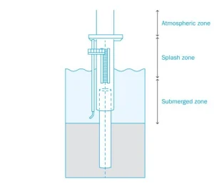
Figure 3 – Schematic representation of marine corrosion zones
Atmospheric zone
In the atmospheric zone, marine structures are exposed to airborne chlorides and therefore at risk of chloride-induced atmospheric corrosion. The marine atmosphere is a demanding environment in which factors such as atmospheric salt content, temperature, and relative humidity affect the corrosivity. These factors are mainly dependent on geographical location. Sheltered conditions where rainwater is not able to naturally clean the surfaces of the structures will lead to a more severe situation.
In the atmospheric zone, corrosion is commonly controlled by using corrosion-resistant alloys or protective coatings. A variety of stainless steels can be used in this zone depending on the corrosivity of the environment and the design of the structures. It is also important to note that the surface roughness of stainless steels can have a significant impact on their performance since a smoother surface typically offers higher corrosion resistance to atmospheric corrosion.
In less aggressive marine atmospheres, lean duplex stainless steels like Forta LDX 2101, Forta DX 2304 and Forta EDX 2304 may be the most cost-effective options. They can be expected to perform well if there is natural cleaning by rainwater and the design does not contain severe crevices. Otherwise, a higher corrosion-resistant duplex stainless steel like Forta DX 2205 may be better.
Splash zone
The splash zone is an extremely aggressive environment. Designing structures in this zone is recognized as a critical challenge. For carbon steel, the highest corrosion rates occur in this zone, but this is not necessarily the case for stainless steel.
In the splash zone, the structures are exposed to wetting by oxygen-rich seawater, wet-dry cycles and UV radiation. The wet-dry cycles can increase chloride contents as the water evaporates, leading to highly severe conditions. Furthermore, structures may be subjected to erosion due to spray, waves and tidal actions, as well as mechanical stresses due to ice drifting, collisions, and floating debris.
Corrosion protection of carbon steel structures in the splash zone requires special consideration. The most common way to protect carbon steel against corrosion is to combine coating with a corrosion allowance. In cases where protective coatings are applied, the risk of mechanical damage, such as wear or scratching of the coating must be considered. Once the coating is damaged, a process of preferential corrosion in the exposed area of the base metal can be accelerated by the galvanic coupling formed. Cathodic protection is not reliable in the splash zone due to the lack of continuous contact with the electrolyte (seawater). In this zone, high-performance stainless steels are reliable alternatives to carbon steel. Depending on how aggressive the conditions are, Forta DX 2205 and Forta SDX 2507 may be options
(Excerpt from an interview with Outokumpu)